
Paper l Vibration Tests of 3D Printed Satellite Structure Made of Lattice Sandwich panels
Xiaoyu Zhang, Hao Zhou, Wenhua Shi, Fuming Zeng, and Huizhong Zeng
Beijing Institute of Spacecraft System Engineering, Beijing, CAST, 100094, China
and Geng Chen, RWTH Aachen University, Aachen, 52068, Germany
- Introduction
Lattice sandwich structures arouse much attention in recent two decades because of their outstanding performance in stiffness, strength, energy absorption and the multifunctional design [1-4]. When subjected to a deformation dominated by stretching, lattice sandwich structures demonstrate preferable weight-efficiency compared to bending dominated structures such as honeycomb sandwich structures [5-7]. Various techniques can be implemented to fabricate lattice sandwich structures, such as investment casting, deformation forming, woven metal textiles [8-10]. However, traditional manufacturing techniques cannot achieve a satisfactory precision and geometrical complexity that are oftentimes simultaneously required by satellite structures. In recent years, the development of additive manufacturing techniques, such as selective laser melting and electron beam melting, make the high- precision lattice structures become reality [11-13]. The geometric precision of the lattice has been reduced to submillimeter scale. The deformation behavior of lattice sandwich plate has been studied via both numerical analysis and experimental testing. It is found that multiple factors such as the parent material, the shape and size of the cell, as well as the connectivity can influence the mechanical properties of the lattice sandwich plate [5]. In aeronautic and aerospace applications, an increasing number of brackets based on lattice sandwich structures have been designed. However, to our best knowledge, the large-scale assembly structure such as satellite structure based on lattice sandwich structures has not been yet verified by experiments.
In this paper, a lightweight satellite structure based on lattice sandwich panels is designed. In this satellite structure all panels are manufactured from aluminum alloy AlSi10Mg by direct metal laser melting. The dimensions of the structure are 400×400×400 mm3, while its mass and carrying capacity reach 8 kg and 104 kg, respectively. The structure’s weight-to-satellite weight ratio is 7.7% in comparison to the ratio about 15~25% of minisatellites (satellites with the weight in the range from 100 kg to 500 kg) made of traditional aluminium honeycomb sandwich panels. Results of vibration tests reveal that the satellite structure could endure vibration loads entailed by the rocket launching.
- Design and Fabrication of the Satellite Structure
The design flow of the satellite structure made of lattice sandwich panels is as shown in Fig. 1.
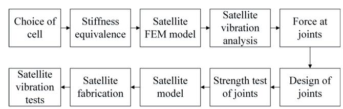
Fig. 1 Design flow of the satellite structure made of lattice sandwich panels
In the “Choice of cell” process, the lattice cell of the satellite structure is chosen according to the application requirement. In the “Stiffness equivalence” process, the lattice core layer is simulated with a homogeneous material layer with the equivalent stiffness. In the “Satellite FEM model” process, the satellite structure is modeled by shell elements as well as solid elements and MPC elements. In the “Satellite vibration analysis” process, the sinusoidal vibration and random vibration loads are applied to the FEM model. In the “Force at joints” process, the force at joints between panels, between equipments and panels, and between satellite and rocket are calculated. In the “Design of joints” process, the joint structures are designed as solid surrounded by small cells rather than large cells to improve the local mechanical strength. The designed bearing capacity of joint structures should be larger than the force at joints calculated in the former process. In the “Strength test of joints” process, the joint structures with the lattice sandwich panels are tested with testing machine. The tensile strength of the joints are obtained and verified by experiments. In the “Satellite model” process, the satellite structure composed of lattice sandwich panels is built with 3D modeling software. In the “Satellite fabrication” process, the satellite structure composed of lattice sandwich panels is fabricated with direct metal laser melting technique. In the “Satellite vibration tests” process, the sinusoidal vibration and random vibration tests are conducted.
The superiority of satellite structure made of lattice and its compare with honeycomb are shown in Table 1. Satellite structure made of lattices has advantages in aspects such as stiffness, strength, connections, special-shaped structural configuration, multifunctional-property, light-weight property and fabrication cycle.
Table 1 Compare between satellite structure of the same weight made of lattice and honeycomb

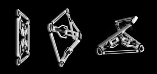
Fig. 2 The lightweight satellite structure made of lattice sandwich structures
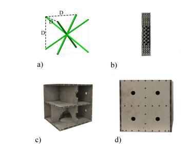
The lattice cell of the satellite structure is pyramidal, as shown in Fig. 2(a). This type of cell has the advantage of low relative density and high stiffness-to-weight ratio [14]. Relative density and effective elastic modulus of this lattice type yield:
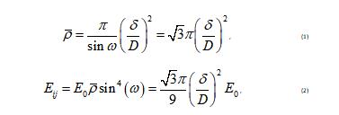
where is the angle between the lattice struts and the horizontal plane, the diameter of the strut, the dimensions of the lattice, the elastic modulus of the parent material. The diameter of the lattice struts adopted in the present study is 0.5 mm, which is the minimum value that we can achieve on our current device with a permissible shape and surface quality. Lattices with even smaller diameters can also be produced but the discreteness in mechanical properties become prominent. The dimensions of the lattice cell in present work is 5×5×5 mm3 (half or third of the thickness of the panels, called large cell) in most region for the aim of light-weight and 2.5×2.5×2.5 mm3 (quarter or sixth of the thickness of the panels, called small cell) in local regions in vicinity to the thread joint for the strong connection.
The lattice sandwich panels are made by the lattice core and face sheets as shown in Fig. 2(b). The face sheets significantly strengthened the structure and make it mechanically stable when subjected to complex loads. The thickness of top and bottom face sheets are both 0.4 mm. The thickness of the bottom panel is 15.4 mm and all rest panels are 10.4 mm. The reason to design a bottom panel with a much greater thickness is to prevent structural failures caused by insufficient load bearing capacity. The local region in adjacent to screw joint is designed as solid surrounded by small cells rather than uniform large cells to improve the local mechanical strength. One can notice from Fig. 2(c) that three horizontal panels (top panel, middle panel, bottom panel) and one vertical panel are designed as a whole part named the main structure. Meanwhile, as shown in Fig. 2(c) and (d), the four inner diaphrams and four outer panels are designed purposely as a component that can be dismountable from the main structure. The dismountable inner diaphrams and outer panels significantly facilitate the installation of the equipments inside the satellite and they can be connected to the main structure through screw joint at the edges of each panel. The distance between neighboring joints is about 50 mm.
The satellite structure is fabricated with selective laser melting technique by using a Concept X-line 1000R equipment with the maximum forming dimensions of 630×400×500 mm3 made by the Concept Laser Company. The raw material used is AlSi10Mg powder. The elastic modulus and yield strength of standard specimens produced by the same process are measured by the uniaxial tensile test and yield 70 GPa and 220 MPa, respectively. We choice AlSi10Mg because its superior stiffness-to-weight and heat dissipation performance compared to other metals such as titanium alloy. The 3D printing method avoid a large amount of adhesives between face sheets and core, and those around connection inserts in traditional honeycomb sandwich panels. Therefore, the stiffness-to-weight ratio of the 3D printed minisatellite structure made of lattice sandwich panels could be superior to traditional minisatellite structures made of aluminium honeycomb sandwich panels.
After all panels are fabricated separately, the satellite is assembled by screwing steel blocks to top, middle and bottom plates of the satellite. The block placed on each plate is 32 kg, therefore the sum of them is 96 kg in total.
III. Vibration Tests of the Satellite Structure
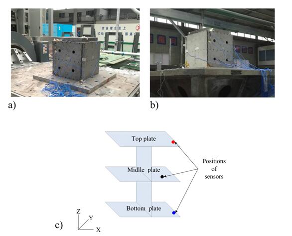
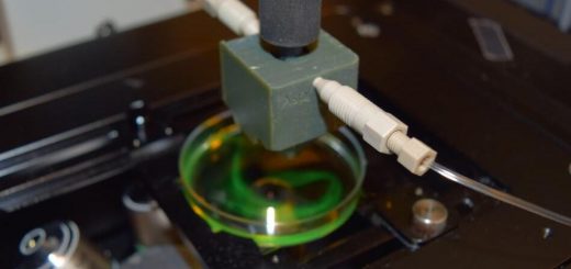
Fig. 3 The photos of vibration tests, (a) horizontal direction; (b) vertical direction; (c) positions of acceleration sensors.
To examine the structure’s ability to endure the vibration loads resulted from the rocket launching, the vibration tests are conducted. The photos of the vibration tests are presented in Fig. 3(a, b). Details of sinusoidal and random vibration loads are outlined in Tables 2 and 3. It is important to note that the vibration loads are applied in X (horizontal) and Z direction (vertical) successively. The Y direction test is omitted because, by neglecting the weak anisotropy (less than 5% in strength) of the printed AlSi10Mg [15], it is justified to consider the structure as quad symmetry and therefore the responses in Y direction as identical to the X direction.
The frequency of the sinusoidal vibration is increased monotonically from 5 to 100 Hz. The maximum magnitudes of the loads are 0.69 g (from 8 to 100 Hz) in the X and 0.805 g (from 8 to 100 Hz) in the Z direction. The increasing rate of the excitation is 2 Oct/min (Octave per minute). i. e. the frequency of the sinusoidal vibration becomes quadruple in each minute.
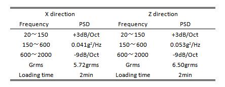
The frequency of the random vibration loads ranges from 20 to 2000 Hz. The maximum power spectral density (PSD) of the random vibration loads is 0.041g2/Hz (from 150 to 600 Hz) in the X direction and 0.053g2/Hz (from 150 to 600 Hz) in the Z direction. The Root-Mean-Square (Grms) of the random vibration loads are 5.72 grms in the X direction and 6.50 grms in the Z direction. The loading time is 2 minutes for each direction.
Table 2 Sine vibration loads
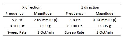
Table 3 Random vibration loads
Three acceleration sensors are glued to the satellite structure to measure the acceleration responses. The acceleration responses of the panels are significative for the structural design of equipments intended to be carried by the satellite into the space. The positions of three sensors are shown in Fig.3(c), i. e. on the edge of top plate, center of middle plate and edge of bottom plate, respectively.
- Results and Discussions
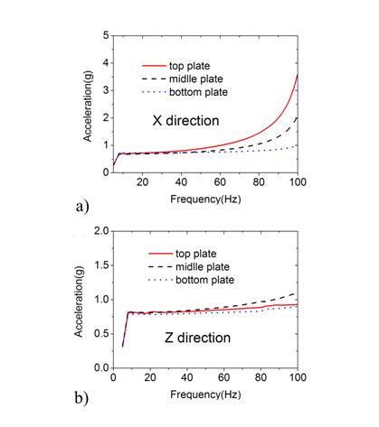
Fig. 4. Acceleration response stimulated by the sine vibration loads, (a) X direction and (b) Z direction.
The acceleration response in the X direction stimulated by the X direction sinusoidal vibration loads are plotted in Fig. 4(a). It can be seen that the acceleration response increases along with the frequency from 5 to 100 Hz. The acceleration response of the top plate is greater compared with the middle plate, while the middle plate is greater than the bottom plate as well. At 100 Hz, the response ratio of the top, middle and bottom plates is about 3.4/2.0/1.0. The peak valued response in the X direction is 3.5 g. The acceleration response in the Z direction stimulated by the sinusoidal vibration loads in the Z direction are plotted in Fig. 4(b). It can be seen that, same as the previous case, the acceleration response increases with the frequency from 5 to 100 Hz. The acceleration response of the middle plate is greater compared to the top plate. It is because that the distance between the middle sensor and the edge of middle plate is larger compared to the one occurred on the top plate. However, the maximum response in the Z direction (1.1 g) is much smaller than the maximum response in the X direction (3.5 g). The discrepancy between the acceleration responses in the Z direction associated with three plates is much smaller, which is only about 0.2 g.
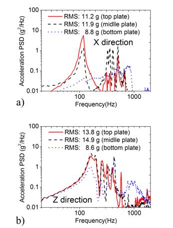
Fig. 5. Acceleration response stimulated by the random vibration loads, (a) X direction and (b) Z direction.
The acceleration response stimulated by the random vibration loads are plotted in Fig. 5. The RMS acceleration of the top, middle and bottom plates is 11.2 g, 11.9 g, and 8.8 g in the X direction test. In contrast, these values yield 13.80 g, 14.9 g, and 8.6 g during the Z direction test. It can be seen that the acceleration response of the bottom plate is more insignificant compared to both middle and top plates.
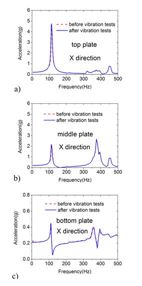
Fig. 6. Low-magnitude X direction vibration response comparison before and after vibration tests, (a) top plate, (b) middle plate and (c) bottom plate.
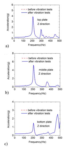
Fig. 7. Low-magnitude Z direction vibration response comparison before and after vibration tests, (a) top plate, (b) middle plate and (c) bottom plate.
To check whether the structure has been damaged by the vibration loads, the low-magnitude sinusoidal resonance scan was performed [15]. The theoretical basis of this method is that the structure’s stiffness change can induce the variation of the resonant frequency [16-17]. In case of critical damage, the resonant frequency decreases obviously. Otherwise, the resonant frequency will remain the same. According to this method, the low-magnitude sine vibration loads (0.2 g, from 5 to 500 Hz, 4 Oct/min) are imposed on the structure both before and after the vibration tests clarified in Table 2 and Table 3. The acceleration responses recorded by sensors under two low-magnitude sine vibrations are compared to each other. The results obtained from all three sensors are presented in Fig. 6 (X direction) and Fig. 7 (Z direction). The first order natural frequencies in the X and Z directions are 120 Hz and 210 Hz, respectively. It can be seen that the acceleration response before and after high-magnitude vibration coincide with each other. Some minor mismatches in Fig. 6 and Fig. 7 may arise from the changes in the pre-stress state around screws between panels resulted from the assembling process. For the satellite structures made of lattice sandwich panels, the weight of the adhesives and structural insert parts used in aluminum honeycomb panels is reduced, the saved weight can both increase the face sheet thickness and the stiffness of the core layer of the sandwich panels. More than that, the whole printing of structural joint and panels instead of the traditional structural inserts with adhesives can obviously increase the stiffness of the satellite structure. Therefore, the resonant frequency of the satellite structure made of lattice sandwich panels can be significantly higher than that made of aluminum honeycomb panels of the same weight. Moreover, the lattice structures avoid the frequent shear failure of honeycomb core occurred in traditional satellites. After the vibration tests, the satellite structure was disassembled and inspected visually. In this stage, neither has any fragment been noticed to drop out from the panels nor have other damages been detected. Therefore, it is justifiable to conclude that the structure has not been damaged during the high-magnitude vibration tests. That is to say, the light-weight satellite structure made of lattice sandwich panels manufactured by the selective laser sintering technique could sustain the vibration during the rocket launching.
- Conclusions
To summarize, the light-weight satellite structure of a size 400×400×400 mm3 and completely made of lattice sandwich panels was designed and fabricated by selective laser sintering technique. The structure’s weight-to-satellite weight ratio reaches 7.7%, which is much superior to the ratio 15~25% of minisatellites (satellites with the weight in the range from 100 kg to 500 kg) made of traditional aluminium honeycomb sandwich panels. When this satellite structure is submitted to a high frequency loading whose amplitude is comparable to the real service condition, the unchanged eigen frequencies confirm that no structure degradation would take place during the testing. The advantages of present structures can be summarized as follows: 1) Excellent stiffness-to-weight ratio property. 2) High strength at joint position with large concentrated force. 3) Small amount of structural connections. 4) The fabrication cycle is quite short because of avoiding the bonding process between face sheets and core as well as the structural inserts embedding process.
Acknowledgments
This project was financially supported by the Young Elite Scientists Sponsorship Program from China Association for Science and Technology. The authors acknowledge the supports from Beijing Institute of Spacecraft System Engineering and Beijing Key Laboratory of Intelligent Space Robotic Systems Technology and Applications.
References
[1] Gibson, L. J. and Ashby, M. F., Cellular Solids: Structure and Properties, Cambridge University Press, Cambridge, 1999.
doi: 10.1017/CBO9781139878326
[2] Schaedler, T. A., Jacobsen, A. J., Torrents, A., Sorensen, A. E., Lian, J., Greer, J. R., Valdevit, L., Carter, W. B., Ultralight Metallic Microlattices, Science, Vol. 334, No. 6058 , 2011, pp. 962-965.
doi: 10.1126/science.1211649
[3] Yuan, W., Song H.W., Wang X., and Huang C.G., AIAA Journal, Vol. 53, No. 4, 2015, pp. 948 -957.
doi: 10.2514/1.J053246
[4] Sing, S. L., Yeong, W. Y., Wiria, F. E., and Tay, B.Y., Characterization of Titanium Lattice Structures Fabricated by Selective Laser Melting Using an Adapted Compressive Test Method, Experimental Mechanics, Vol. 56, No. 5, 2016, pp. 735-748.
doi: 10.1007/s11340-015-0117-y
[5] Rashed, M. G., Ashraf, M., Mines, R. A. W., and Hazell, P. J., Metallic microlattice materials: A current state of the art on manufacturing, mechanical properties and applications, Materials and Design, Vol. 95, 2016, pp. 518-533.
doi: 10.1016/j.matdes.2016.01.146
[6] J. Caulfield, A.M. Karlsson, D.J. Sypeck, Crushing of a textile core sandwich panel, AIAA Journal, Vol. 44, No. 6, 2006, pp. 1339–1344.
doi: 10.2514/1.17156
[7] Deshpande, V. S., Ashby, M. F., and Fleck, N. A., Foam topology: bending versus stretching dominated architectures, Acta Materialia, Vol. 49, No. 6, 2001, pp. 1035–1040.
doi: 10.1016/S1359-6454(00)00379-7
[8] Wadley, H. N. G., Fleck, N.A., and Evans, A.G., Fabrication and structural performance of periodic cellular metal sandwich structures, Composites Science and Technology, Vol. 63, No. 1, 2003, pp. 2331–2343.
doi: 10.1016/S0266-3538(03)00266-5
[9] Radford, D. D., Fleck, N. A., and Deshpande, V. S., The response of clamped sandwich beams subjected to shock loading, International Journal of Impact Engineering, Vol. 32, No. 6, 2006, pp. 968–987.
doi: 10.1016/j.ijimpeng.2004.08.007
[10] Queheillalt, D. T. and Wadley, H. N. G., Cellular metal lattices with hollow trusses, Acta Materialia, Vol. 53, No. 2, 2005, pp. 303–313.
doi: 10.1016/j.actamat.2004.09.024
[11] Tsopanos, S., Mines, R.A.W., McKown, S., Shen, Y., Cantwell,W.J., Brooks, W., et al., The influence of processing parameters on the mechanical properties of selectively laser melted stainless steel microlattice structures, Journal of Manufacturing Science and Engineering, Vol. 132, No. 4, 2010, pp.1-12.
doi: 10.1115/1.4001743
[12] Gibson, I., Rosen, D.W., and Stucker, B., Additive Manufacturing Technologies: Rapid Prototyping to Direct Digital Manufacturing, Springer, New York, 2009.
doi: 10.1007/978-1-4419-1120-9
[13] Yan, C., Hao, L., Hussein, A., Young, P., and Huang, J., Microstructure and mechanical properties of aluminium alloy cellular lattice structures manufactured by directmetal laser sintering, Materials Science and Engineering: A, Vol. 628, 2015, pp. 238-246.
doi: 10.1016/j.msea.2015.01.063
[14] Fan, F. L., Fang, D. N., and Jing, F. N., Yield surfaces and micro-failure mechanism of block lattice truss materials, Materials and Design, Vol. 29, No. 10, 2008, pp. 2038–2042.
doi: 10.1016/j.matdes.2008.04.013
[15] Tang, M. and Pistorius, P. C., Anisotropic mechanical behavior of AlSi10Mg parts produced by selective laser melting, JOM: the journal of the Minerals, Metals & Materials Society, Vol. 69, No. 3, 2017, pp. 1–7.
doi: 10.1007/s11837-016-2230-5
[16] Pearce, M., Lund, J., Lundin, M., and Lundquist, J., Random vibration tests of the anticoincidence system of the PAMELA satellite experiment, Nuclear Instruments and Methods in Physics Research A, Vol. 488, No. 3, 2002, pp. 536–542.
doi: 10.1016/S0168-9002(02)00562-4
[17] Krishna Murty, A. V. and Viswa Murty, G., Design modifications in vibration problems, Journal of spacecraft and Rockets, Vol. 5, No. 7, 1968, pp. 870–872.
doi: 10.2514/3.29378
[18] Nagaraj, V. T., Changes in the vibration characteristics due to changes in the structure, Journal of spacecraft and Rockets, Vol. 7, No. 12, 1970, pp. 1499-1501.
doi: 10.2514/3.30209

Recent Comments