
Unlock Breakthrough Heat Exchanger Designs with Gyroids
In modern aircraft, fuel spends much of its time in the wings where it gets rather cold. This could cause it to crystallize and clog the system.
However, the chilled fuel gives engineers an opportune way to regulate the temperature of the aircraft’s combustion chamber, mechanical and electrical systems.
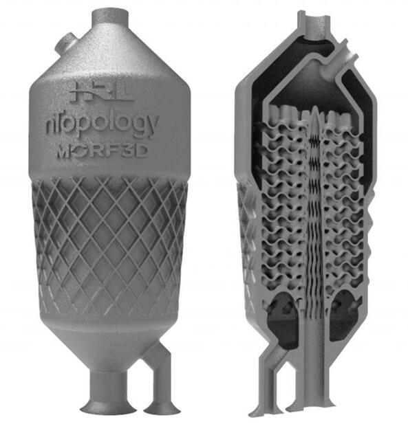 A fuel-cooled oil cooler (FCOC) heat exchanger design. Image via ANSYS.
Engineers can use fuel-cooled oil cooler (FCOC) heat exchangers to transfer thermal energy between the engine oil and fuel to efficiently:
- Get engine oil cool enough to lubricate and chill systems
- Prevent fuel from crystallizing
- Get fuel closer to ignition temperature
Optimizing FCOCs can be a challenge because they need to meet strict size, shape and weight restrictions to fit into an aircraft’s configuration. As such, engineers tasked to optimize heat exchanger designs are limited to two options:
- Maximizing the surface area of the inner walls
- Limiting the thickness of the inner walls
Traditionally, shell and tube heat exchanger designs were the most viable option because they are easy to design and fabricate.
However, engineers can now use additive manufacturing, topology optimization and computational fluid dynamics (CFD) to build, shape, optimize and evaluate designs that were previously impossible to produce.
![]() How a Minimal Surface Lattice Improves Heat Exchanger Performance
How a Minimal Surface Lattice Improves Heat Exchanger Performance
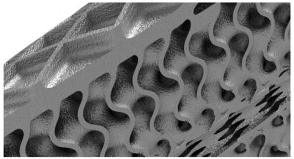 The internal surface of the heat exchanger is based on a gyroid.Image via ANSYS.
One way engineers can maximize the surface-area-to-weight ratio is to use nTopology’s nTop Platform. With this software, they can generate and design the interior of an FCOC using triply periodic minimal surfaces (TPMS).
For instance, gyroids are a type of TPMS that can be used to define an internal volume that maximizes surface area and strength while minimizing mass.
Using nTop Platform’s geometry tool, the engineers were able to improve the performance of the heat exchanger by 150% over traditional geometry.
The engineers wouldn’t be able to use traditional techniques to build the part. However, they can use advanced additive manufacturing techniques to construct the complex shape of the FCOC.
To keep the walls thin, the engineers selected a high strength aluminum alloy specifically tailored for 3D printers. The material’s strength enabled them to halve the wall thickness while maintaining critical aircraft structural requirements — like burst pressure.
![]() CFD Simulations Predict the Performance of Heat Exchanger Designs
CFD Simulations Predict the Performance of Heat Exchanger Designs
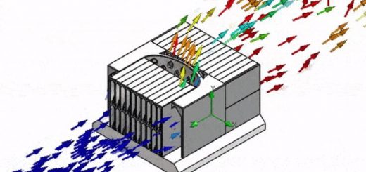
Throughout the iteration phase, the engineers used ANSYS CFX to evaluate the performance of their in-house FCOC heat exchanger design.
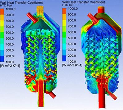 A contour plot of the heat transfer coefficient inside the fuel domain and the streamlines of the oil flow (left). A contour plot of the heat transfer coefficient inside the oil domain and streamlines of the fuel flow (right).Image via ANSYS.
They even developed a repeatable workflow between the nTop Platform and CFX to expedite their iterations and mesh refinements. By coupling this workflow to a design iteration process, engineers were able to increase the performance an additional 12%.
Source: ANSYS

Recent Comments