
Additive Manufacturing and Heat Exchangers
Why are heat exchangers the poster child of additive manufacturing? Here we discuss why additive manufacturing is used for heat exchangers, give design advice and discuss the challenges involved with printing these components.
A heat exchanger is a device that is used to transfer heat between two different fluids. The design of a heat exchanger is often a complex balance between maximizing the surface area of the part but minimizing the pressure drop through the heat exchanger. We’ve already seen many examples of companies leveraging the geometric complexity that additive manufacturing can give us to design complex heat exchanger cores. However, designing heat exchangers that can be verified for any use applications is not simple.
Here we’re going to try and answer three questions:
- Why use additive manufacturing for heat exchangers
- What are some of the design considerations that we need to think about when designing heat exchangers
- What are the performance barriers and challenges to leveraging AM to create high-performance heat exchangers?
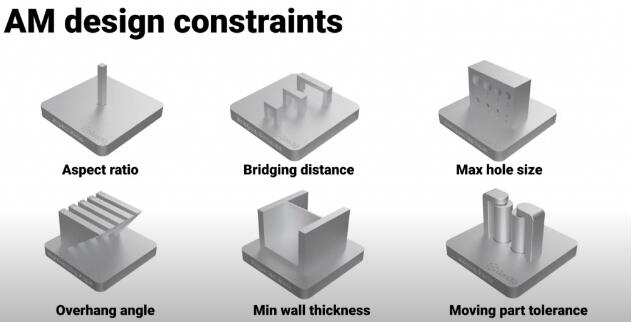
![]() Why are heat exchangers one of the most frequently produced parts using metal additive manufacturing?
Why are heat exchangers one of the most frequently produced parts using metal additive manufacturing?
There are a number of reasons.
- AM has the advantage of being able to produce the heat exchanger core and the manifolding as a single monolithic part. The way we traditionally produce heat exchangers is to create individual fins or plates and bond those together. This is a manual technique and if there’s a failure between any of those brazing joints it can lead to failure of the heat exchanger. It’s therefore advantageous to produce all internal structures within a single manufacturing process.
- Additive manufacturing can be used to create custom shapes and sizes of heat exchangers. This is common in industries like motorsport where many components are packaged into a tight volume. AM is great for this because you can design custom packing and manifolding to fit directly into tight volumes.
- Metal additive manufacturing processes such as laser powder bed fusion have the ability to print very thin-walled materials. It’s possible to successfully produce walls of 0.1 millimetres of thickness. This isn’t without its challenges and often requires R&D on the process parameters to produce these thin-walled structures. However, the thin-walled properties make them ideal for heat exchangers.
- AM can be used to produce heat exchangers out of a wide range of materials ranging from aluminium alloys all the way up to high-temperature alloys such as Inconel 718 and Inconel 625. Other materials such as copper and copper alloys can also be produced using better additive manufacturing processes and the high conductivity of these materials makes them ideal for heat transfer applications such as for heat sinks and heat exchanger devices.
![]() The challenges of designing heat exchangers
The challenges of designing heat exchangers
The design of heat exchangers can be very challenging because heat transfer is governed by three elements:
- Conduction
- Convection
- Radiation
However, if we simplify this heat transfer down into just one element, the conductivity, we can see that the heat transfer is governed by the following equation:

We can see that the heat transfer rate is governed by a number of different things.
- Firstly we’ve got k which is thermal conductivity. This is normally governed by the material selection, so it may seem logical to use the material with the highest thermal conductivity. However, when designing heat exchangers for endless applications there’s normally conflicting specification elements that we need to look at. Thermal conductivity of the material is therefore important, but, we also need to think about strength, the density of the material and the melting point. This helps to find the optimum material for the heat exchanger design.
- Next, we look at the A element. This dictates that we need to try and maximize the amount of surface area used to transfer the heat
- The dx defines the wall thickness of the heat exchanger. The equation shows us that the smaller the wall thickness, the better the conductivity across the wall. Therefore when it comes to designing heat exchangers, the wall thickness is typically a design constraint of the additive manufacturing process.
There are many published guidelines online pertaining to the minimum wall thicknesses for individual processors. The minimum wall thickness for additive manufacturing for laser powder bed fusion (LPBF) materials, the guidelines state, is around 0.5 millimetres. However these are only guidelines and with careful parameter optimisation, we can optimise the minimum wall thickness down to much lower than this.
![]() Different AM designs of heat exchangers
Different AM designs of heat exchangers
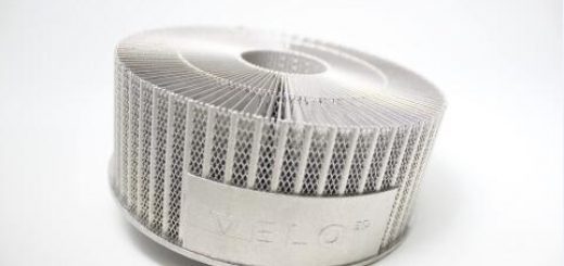
It is popular to leverage lattice materials or lattice structures for heat exchangers because they increase the surface area element to the above equation.
A popular type of lattice for heat exchangers is a TPMS lattice (triply periodic minimal surface.) With a TPMS lattice, we can split the heat exchanger into multiple domains just by using the TPMS equation.

Gen3D can be used to create these TPMS services and below is an example of using Gen3D using the surface lattice and then clicking on the double skin property to give us these two fluid domains.
By changing the cell size and the density of the lattice within Gen3D, you can tune the parameters of your heat exchanger so TPMS lattices can be a wonderful way of increasing the surface area of your heat exchanger.
You must be careful because they can increase the pressure drop across the heat exchanger. This balance between surface area and pressure drop is a constant balance that heat exchanger designers are facing every day,
![]() Challenges throughout the additive manufacturing workflow
Challenges throughout the additive manufacturing workflow
- At the CAD stage, we see challenges in defining large numbers of thin-walled surfaces.
- As we move through the design journey, simulating these heat transfer surfaces can be a challenge. Slicing the models before they can go into the CAD software can be data-intensive
- Printing thin-walled structures can be a risky process that requires careful machine optimisation.
- The biggest challenge is often at the verification and testing stage. How do we ensure all the powder has been removed from the channels and all the walls have been created perfectly in the internals? There’s a number of non-destructive testing techniques such as resonance testing to check for powder or CT scanning to check the integrity of the structure. However, CT scanning can be an expensive process. Also, if we’re producing heat exchangers from dense materials such as Inconel it can even be impossible to penetrate more than a few centimetres into the surface to check the integrity of the parts.
![]() The future of additive manufacturing and heat exchangers
The future of additive manufacturing and heat exchangers
Gen3D has been involved in a project with Aerosint where we collaborated on a project to produce multi-material heat exchangers. Below is a part that we created and you can see that the outside surface of the heat exchanger is printed from stainless steel and the inside surface of the heat exchanger, (which acts as the surface that transfers the heat between the two fluids) is printed from a high conductivity copper alloy.
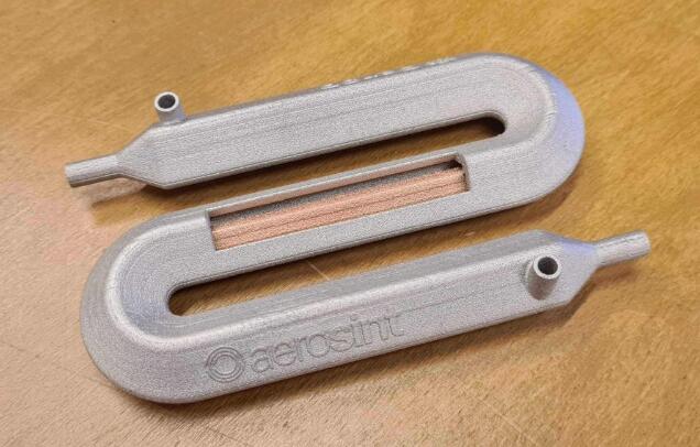
This is just one example of what we might see in future additive manufacturing heat exchangers.
Source: Gen3D
For press release, welcome to send to 3D Science Valley at 2509957133@qq.com

Recent Comments