
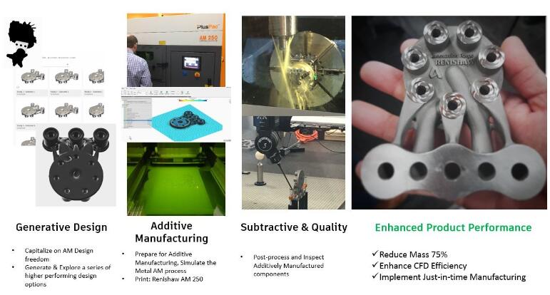
The Case for Design for Additive Manufacturing
Additive Manufacturing (AM) is growing at a rapid clip. The driving force behind this, is the competitive separation that Since additive manufacturing allows us to create products that were never thought possible, we also need a new set of solutions that help us re-imagine our designs to match new production potential. Enter Autodesk generative design, a technology within Fusion 360, which allows users to quickly generate 10’s, 100’s, or 1000’s of CAD-ready, higher performing design options, based on real-world manufacturing constraints. General Motors recently announced that they leveraged generative design to consolidate a traditional assembly from 8 parts to 1 (improving supply chain), create a 40% lighter design that’s also 20% stronger, all while generating over 150 feasible design options.

“We subscribe to the ‘design thinking’ philosophy where quantity is valued over quality in the ideation phase and we think AGD is a HUGE leap forward in design,” said Kenny Cornett, owner of Innovation Forge. “With AGD, we have brought that philosophy to our CAD work and we can now identify form and function early on and use the natural synthesis from a multitude of design options to find the best path forward.”
![]() Cast Study | End-to-End Additive for Hydraulic Manifold
Cast Study | End-to-End Additive for Hydraulic Manifold
For the rest of this article, we will use a generatively-designed Hydraulic Manifold to show workflows, initially created by Kenny Cornett at Innovation Forge (http://i-forge.co/).
![]() Why Additive needs Subtractive
Why Additive needs Subtractive
Some consider additive manufacturing and subtractive manufacturing as competing technologies. In actuality – they are supplemental, and having Subtractive Post processing combined with Metal Additive is in most cases, required.
The reason for that is because Laser Powder Bed Fusion (LPBF) has it’s limitations. While it can produce “impossible to make geometries”, internal lattice structures, and organic designs – it also doesn’t match up with Subtractive Manufacturing in capabilities like surface finish.
- According to industry data, the usual surface roughness values for selectively laser melted parts vary between 15 µm and 40 µm (Metal-AM.com). Depending upon the application, critical geometry may need finishing or polishing
- Additive also has limitations with features like Holes – threaded holes will need to be drilled and tapped afterwards, and holes requiring tight tolerances may need to be machined as well.
For more details on Additive Manufacturing design considerations, view the Renishaw AM Guide or the Canada Makes Metal Additive Design Guide
![]() New Considerations with Generative Design
New Considerations with Generative Design
As if combining two highly specialized technologies in Additive + Subtractive wasn’t enough – organic geometry created through Generative Design can add some additional challenges to the production process
While Organic Geometries created by Generative Design can lead to amazing increases in Product Performance:
1. How do we connect Additive Manufacturing & Subtractive Manufacturing?
2. How do we plan for post-processing with Generative Design?
3. How do you hold those parts during machining post-processing?
4. How do you align to those parts for your Work Coordinate System?
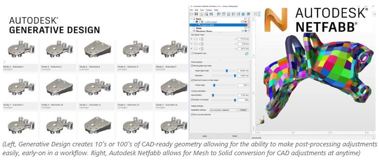
![]() Mesh to Solid | Connecting Additive & Subtractive data
Mesh to Solid | Connecting Additive & Subtractive data
When planning for Additive Manufacturing, with Subtractive Manufacturing post-processing, we need to make both an Additive Manufacturing ready model and a Subtractive Manufacturing-ready model. In either case, data will have to be manipulated. For those working with STL data in Additive this has been traditionally painful – once a file has been converted to an STL mesh, it can be very challenging to do conventional CAD operations needed to plan for Subtractive Manufacturing. This is the importance of Autodesk Netfabb’s and Autodesk generative design within Fusion 360 solutions for Mesh to BRep. Unlike Topology Optimization which usually creates a Mesh, Autodesk’s generative design technology creates a CAD-ready SAT file, allowing engineers to add post-processing allowances, close holes to be drilled later, etc.. More details on Mesh-to-BRep functionality, here.
![]() Planning for Post-processing in Generative Design
Planning for Post-processing in Generative Design
Generative Design technology works by taking input geometries as Preserve or Obstacle geometry, and using Form Synthesis to generate CAD-ready geometries, comparing across a range of materials, that achieve a stated performance increase. For example, minimize mass while keeping a Factor of Safety of 2, for Aluminum, Titanium, Stainless Steel, and Inconel. We can use the input geometries to our advantage, by specifying machining allowances as geometry within the Generative Design process.
In the image below, we are using geometry for our Machining allowances as an extra set of Obstacle Geometries – making it so Generative Design will not add any material in those areas.
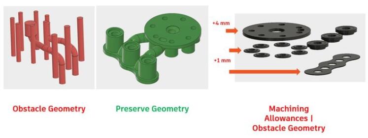
We then take that with the output results, to generate two models:
- Additive-ready, which has machining tolerances added to it
- Subtractive-ready, which has the final expected geometry after machining
![]() Workholding for Additively Manufactured parts
Workholding for Additively Manufactured parts
Now that we’ve generated and printed our organic geometry, we also have to be able to hold in for subtractive post-processing. Since we can shift between Mesh and Solids at anytime, we can use our geometry to create 3D-printed Conformal Jaws as work-holding. We can do that by using our Additive-ready model, and subtracting it from blocks of CAD geometry.
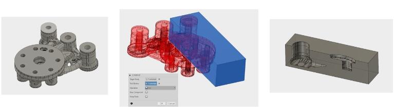
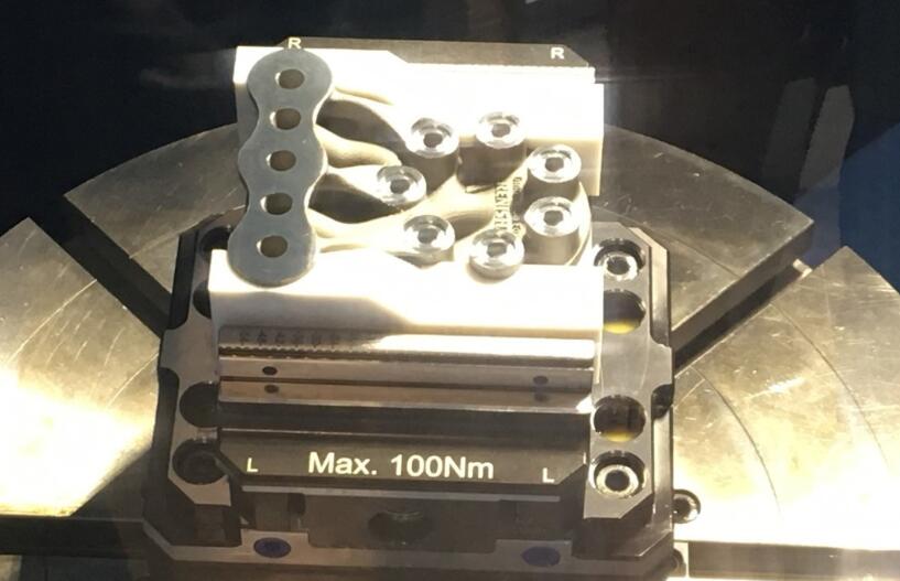
(3D Printed conformal jaws used to tightly hold the printed part for Subtractive finishing. Shown at the Renishaw Canada Solution Center)
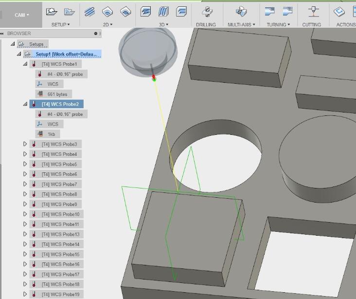
![]() Aligning to Parts
Aligning to Parts
Machine alignment is the process of picking up known points, to specify a machine’s WCS (Work Coordinate System) on a part. This is the basis for toolpaths to reference as a 0,0,0 point. For traditionally produced parts you can align to corners or known points. With Additively created organic geometry it can be more challenging, where there might not be regular CAD geometry to align to. Here we have two options:
(1) we can add additional geometry, just for alignment
(2) we can use alignment tools.
To add additional geometry for alignment, since we can convert between a Mesh and a Solid at anytime, we can use known geometry to add to a design. In Fusion 360 – there are a set of geometries available with the solution that can be easily used for probing, these can be added to your “Additive-ready” part to set the Work Coordinate System. Within just Fusion 360 – we can create generative design input geometries, generatively-design the part, post-process, set probing strategies for CAM, and generate CNC toolpaths. For more details on probing, check here: Fusion 360 WCS Probing Tutorials
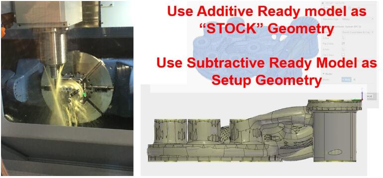
![]() Creating Toolpaths
Creating Toolpaths
Since we have both Additive & Subtractive ready models to start machining, we can specify the Additive ready as the “Stock” Geometry and Subtractive ready as the “Setup Geometry”
More information on getting started with CAM, check out some of the great content created by Tim Paul, Marti Deans, and Lars Christensen: Fusion 360 CAM Adoption Portal.
![]() Outcomes
Outcomes
The results combine the geometric complexity of Additive Manufacturing, with the surface finish and precision of Subtractive Manufacturing.
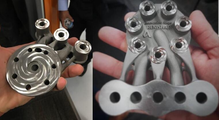
(Final outcome printed and post-processed with Renishaw AM250 at the Renishaw Canada Solution Center)
Sources: Autodesk Netfabb


Recent Comments