
Capability Analysis of Orthopedic Porous Structures Manufactured by Direct Metal Laser Sintering (DMLS®)
![]() INTRODUCTION:
INTRODUCTION:
Reticulated porous structures used to encourage bone ingrowth are a common feature of modern orthopedic implants (Figure 1). Since 2007 additive manufacturing (AM), or industrial 3D printing, has been used to manufacture implants with these types of interconnected porous structures due to the benefits of designing structures closely mimicking cortical and cancellous bone, and cost advantages compared to foam manufacturing. However, current regulatory guidelines for evaluating porous structures published in 1997 and standards used to evaluate these structures are based on historic sintered bead and plasma spray coating processes. Due to the present lack of standards regarding porous structures made with AM, typical verification methods may underestimate the effect of the machine process parameters on the desired characteristics of the porous structure. The purpose of this study was to evaluate the change in dimensional accuracy of the test coupons (Figure 2) when subjected to process parameter variation and the repeatability of their mechanical properties when manufactured under serial production. This study characterizes the effect of the additive manufacturing machine process parameters on overall porous structure density and mechanical properties of a laser sintered porous structure coupon.
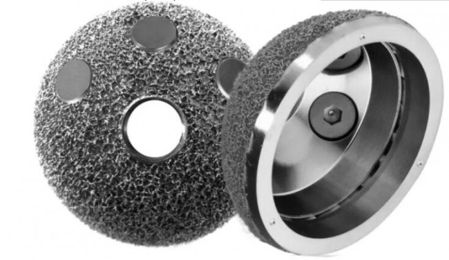 Figure 1 – Example of porous acetabular cup using DMLS® process (Permedica, Italy)
![]() METHODS:
METHODS:
Porous coupons for compression test derived from the standard ISO 13314 were built using optimized exposure strategy and layer thickness of 60µm for maximal building speed. The project began by pre-selecting the geometry based on requirements for buildability. The software nTopology ® (New York, NY) was used for the construction, resulting in a voronoi configuration that met all the requirements derived from the standard and design specifications established for this study (Figure 2). The final configuration of the designed part was a stochastic porous structure with 62.5% porosity, 350 micron strut thickness and mean pore size of 600 microns.
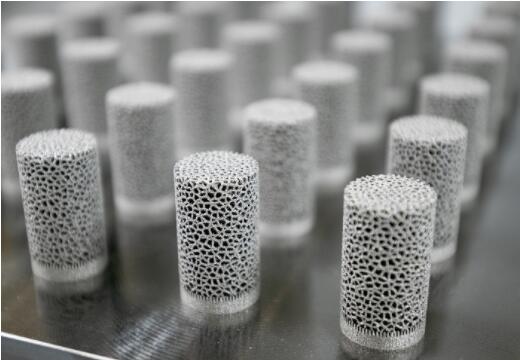 Figure 2 – Geometry of the as-built compression test coupons
Since the standard machine parameters of a DMLS® system are parametrized for general solid structures, a series of three Design of Experiments (DoE) were performed in order to find suitable porous structure exposure parameters. This was done by varying laser power and scan speed (Figure 3). The behavior of parameter variation and their effects on part requirements were evaluated and the final parameter configuration was selected based on the ability to manufacture parts close to the initial design specification. The optimized build parts had a porosity of 71%, average strut thickness of 330 microns and average pore size of 750 microns. Since the coupons were fully porous, strut density was taken as measurement of solid density using Archimedes Principle resulting in 99.7% average solid density.
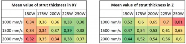 Figure 3 – Process parameters have different effects on the strut thickness in X & Y vs. Z direction. Laser power and scan speed was varied in a DoE to determine best parameter sets for the designed porous structure considering both x-y and z direction.
The result of this DoE supports the theory in literature that laser power has the greatest influence on porous constructions, especially on strut thickness in Z direction (Figure 4). The growth in Z direction led to porosity deviations and oval struts. However, the consistent strut density showed process stability and the ability to build dense struts with parameters designed for porous structures. This DoE study reached satisfactory results and further development of process parameters for a specific porous structure can lead to part dimensions matching the design specifications.
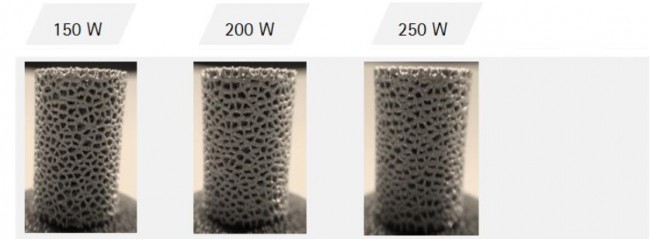 Figure 4 – Influence of laser power on strut thickness (Z). With an increase of energy input the overall solid density increases due to larger struts in the Z-direction.
Next, the parameters selected in the DoE were applied to create a capability assessment. Three identical jobs were built on a DMLS® machine (EOS M 290 EOS GmbH, Krailling, Germany, Figure 5). Each job was composed of 64 fully porous cylindrical parts segregated in 16 identical quadrants over the building platform and evaluated in as-built condition according to their variation between and within jobs. A total of 192 coupons were built using Ti-6Al-4V ELI material (EOS Titanium Ti64ELI, EOS Oy, Turku, Finland). Cleaning was performed using compressed air followed by ultrasonic bath. Clean parts were defined as displaying no trapped powder within the structure under stereological evaluation. From the built parts, 128 were nondestructively tested using the Archimedes principle, 96 of the test samples were tested destructively by compressive mechanical testing (ISO 13314), and 32 were cross-cut, embedded and post processed for stereological evaluation.
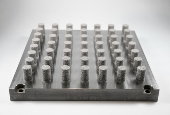 Figure 5 – Positioning of the porous test coupons on the build plate of the EOS M 290
![]() RESULTS
RESULTS
Process capability measures process stability and how close it is performing to the specification limits. The results displayed in Figures 6 for structure relative density, maximum compressive strength and quasi-elastic modulus respectively were plotted in a process capability report with their corresponding specification limits derived from the minimum process capability indices of 1.33 for a serial production scenario. Although this configuration does not allow the unilateral evaluation of process centricity (Ppk), it does allow evaluation of normality, range, and process capability. The tested coupons over-performed the process quality requirements by reaching capability indices of 1.33 relating to an existing process, whereas at this stage, indices of 1.67 for a new process would be required. Finally, the chosen process parameters demonstrated parts built over different jobs and positions on the build platform had less spread than expected for this pre-serial production phase. The continual improvement of the production process can eventually lead to even better results compared to the current outcome of 99.99% process yield and only 63 parts per million expected in process fallout. It should be noted that the change in porosity for the 128 parts built in the DMLS® process comprised only 1.76% in absolute value change, where traditional foaming manufacturing processes are expected to have up to 10% change.
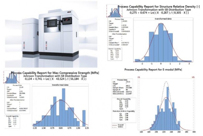 Figure 6 – On the top left: EOS M 290 DMLS® machine used to build the porous test coupons. On the top right: Capability of the structure relative density [-] of such coupons. On the bottom left: Capability analysis for maximum compressive strength [MPa] of such coupons. On the bottom right: Capability of the quasi-elastic modulus [MPa] of such coupons.
![]() SIGNIFICANCE / CLINICAL RELEVANCE:
SIGNIFICANCE / CLINICAL RELEVANCE:
As more porous applications for laser based 3D printing are introduced to the medical field, it is important to understand the effect that the AM machine process parameters have on their mechanical properties and how they behave in serial production. The ultimate goal is to validate porous structures applied not only as a coating but as structural part of the implant.
Source:linkedin
Recent Comments