Additive Manufacturing of Support-Free Shrouded Impellers
Traditionally, direct metal laser sintering (DMLS) requires support structures to avoid deformations due to thermal stresses and conduct the heat away from the melt pool. These supports are part of the design and manufactured as a whole. After building, the support structures are removed and thrown away. However, at EOS Additive Minds, we have developed a variety of process optimization techniques to produce 3D printed parts without support structures.
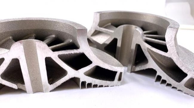
Support-free additive manufacturing saves a large amount of time in the post-processing stage as there are no additional supports to remove. In the case of manual removal, this also frees up the employee to apply their time and energy elsewhere. Manufacturing parts without support structures also reduces the amount of materials wasted, since nothing is thrown away and every aspect of the design of part and support is necessary. However, this isn’t a straightforward process, and for years our experts have worked on the challenge of support-free designs. In this article we show how the support-free methodology was utilized to build an impeller.
![]() Design considerations
Design considerations
The impeller used to demonstrate the support-free building and the capabilities of the DMLS process, was designed by EOS Additive Minds and has a diameter of 150mm with twelve blades with overhang angles down to 10 degrees.
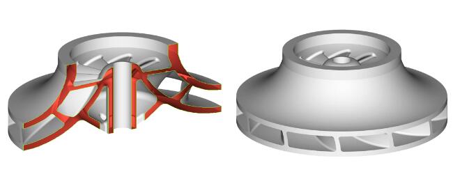 The Design of the impeller [Source: EOS]
![]() Orientation & Supports
Orientation & Supports
Impellers are often printed in an angled orientation in order to avoid internal supports since these are very difficult to remove. However, this orientation typically results in higher building times, in-homogeneous surface quality and the roundness of the part suffers. A flat orientation offers several advantages, such as a lower building time, better roundness and accuracy and a more homogeneous surface quality throughout the part. However, the low overhangs would typically require high amounts supports. With current DMLS processes, larger overhangs with angles of less than 35° need to be supported. The supports are needed to dissipate the heat from the melt pool to compensate recoating forces and internal part stresses.
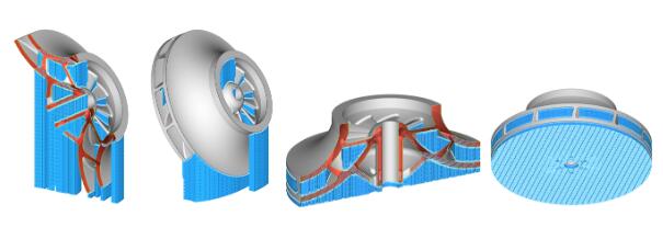 The traditional orientation and resulting support structure (right), angled case (left) [Source: EOS]
![]() Support-free design optimization
Support-free design optimization
With advanced techniques the necessity of internal supports can be reduced significantly. One important aspect therefore is the design optimization for AM. Whilst internal supports can be avoided mainly by using adjusted exposure strategies, external support structures are usually still required.
Instead of using a solid extrusion, the bottom of the part can be modified with self-supporting arches and thin walls to ensure a strong platform connection and prevent deformation during the build. This allows to use less material as with traditional supports while offering high strength and improved machinability. The outer diameter of the impeller is closed to provide more stiffness to the part while building and to prevent loss of geometrical accuracy on the edges of the outlets. For this impeller, the advanced design requires 15% less material while having machining optimized and self-supporting structures and no internal supports.
 The traditional vs Support-free building [Source: EOS]
![]() Process Optimization
Process Optimization
The impeller has been built with what is called the high energy DownSkin method (exposure type used to build over-hanging surfaces). In essence, this method increases the energy density input of the DownSkin exposure by increasing the laser power while adjusting other DownSkin parameters as well. This results in bigger yet more stable melt pool, especially when building overhangs on top of loose powder. The method has been successfully used for many materials that are frequently used to build impellers (e.g. Ti64, 316L, AlSi10Mg, In718, …).
Thereby, it is assured that all critical angles can benefit from this optimized parameter. Unlike other Support-free techniques, the High Energy DownSkin Method does not sacrifice the build rate and therefore the business case to avoid supports.
Without any counter measures, the high energy DownSkin method results in parts which are oversized in z-direction in the DownSkin area due to the deeper melt pools. Parts can be brought to the right size through post processing or through adjustment of the design. The DownSkin is also relatively rough but the roughness is homogeneous which facilitates bulk surface treatment techniques like Abrasive Flow Machining. There is also hardly any porosity (see picture below) and the porosity is limited to the DownSkin. Therefore, the bulk mechanical properties are unaffected and you can still rely on the high quality InFill processes developed by EOS. Therefore, also no secondary processes like Hot Isostatic Pressing are needed to obtain sufficient mechanical properties.
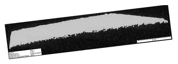 Crosscut high energy DownSkin exposure [Source: EOS]
The as-build quality can be seen in the following pictures below.
 Pictures highlighting the DownSkin quality of the high energy DownSkin approach [Source: EOS]
![]() Post-processing (abbrasive flow machining, AM Metals)
Post-processing (abbrasive flow machining, AM Metals)
Abrasive flow machining is a commonly used surface finishing technology for flow related applications and internal geometries. An abrasive medium is pushed through the part clamped in a fixture. The abrasive particles in the media grind and polish the surfaces along the flow path. As preparation for the internal surface finishing, the closed, outer diameter needs to be machined open, diameter and part height adjusted to the fixture used for the AFM process. After the pre-machining the part is clamped, and the abrasive medium is pushed through the part with help of the fixture. After the AFM process, the impeller is machined to its final dimensions.
Images of final part, processed with abrasive flow machining (AFM)
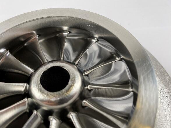 Top View of impeller after AFM [Source: EOS]
 Detailed picture of UpSkin Surface after AFM [Source: EOS]
 Detailed picture of DownSkin Surface after AFM[Source: EOS]
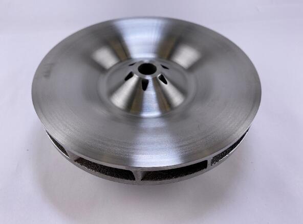 Impeller bottom surface after machining [Source: EOS]
Source: Davy Orye from EOS
For press release, welcome to send to 3D Science Valley at 2509957133@qq.com

Recent Comments