
Simulating Performance Of CT-Scanned AM Parts
While Additive Manufacturing (AM) has many advantages for industry, including the ability to optimize the design of high-value parts and other components, it also comes with some risks. When used in manufacturing, it is possible that parts deviate from their idealized CAD original designs, resulting in unexpected defects in the final as-manufactured part. This uncertainty works against some of the more general benefits of AM for adding flexibility to manufacturing workflows, and for creating more customized parts that can improve performance.
The future performance of AM parts can be mitigated using Finite Element Analysis (FEA), whereby designs can be virtually evaluated prior to manufacturing. AM parts can also be scanned using computed tomography (CT) to identify and measure internal defects and other features that might affect the functionality of a component. However, the use of these different techniques tends to be fragmented, without a clear workflow for linking the stages of AM, scanning, and simulation.
Synopsys, Inc., North Star Imaging (NSI), and ANSYS have collaborated on a new workflow to tackle this problem. Synopsys’ Simpleware software is used to generate FE meshes from NSI’s CT scans of AM parts, with the goal of identifying defects and simulating part performance in ANSYS software. The workflow is already showing great promise for academic research and industrial manufacturing, with the University of Pittsburgh and Moog, Inc. using it to build insights into lightweight brackets and an impulse manifold.
![]() Reducing Complexity for AM to Simulation Workflows
Reducing Complexity for AM to Simulation Workflows
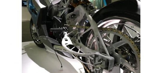
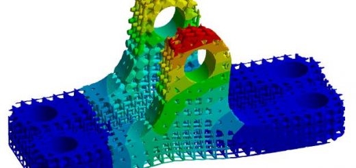
For Synopsys, NSI, and ANYS, it was necessary to connect several existing workflows involving AM parts. Research at the University of Pittsburgh by Albert To offered an excellent test case through their work on optimizing industrial parts using CAD design and FE simulation. Albert To’s group at Pittsburgh already use ANSYS’s homogenization and structural optimization tools to modify the design of a bracket geometry suitable for aerospace applications. These tools were used to build a bracket with a weight-saving lattice structure. After validating the design using a homogenized model, the new part was manufactured in titanium alloy in an EOS direct metal laser sintering (DMLS) powder bed AM machine.
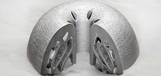
 Finite element mesh created in Simpleware software
Although this method enables multiple design iterations to be experimented with to create a proof-of-concept, it does not always capture differences between the as-designed and as-built part. To identify these differences, the Pittsburgh part was first CT-scanned by NSI to an excellent level of detail. Acquiring the CT data of the parts is a relatively straightforward process, taking just two hours using NSI’s Inspection Services Lab in Minnesota.
The CT data was imported to Synopsys Simpleware software to be processed and segmented to identify regions of interest. This step makes it easier to create a model with only the parts of the scan that are needed for the application: in this case, Simpleware software segmented the part from its surrounding air space. An optimized 3D surface and volumetric FE mesh were generated in Simpleware software. At this stage, the Synopsys-NSI-ANSYS workflow becomes more efficient than other workflows using image data, as Simpleware software directly exports simulation-ready meshes to FE solvers, removing the need for manual fixes on the exported file.
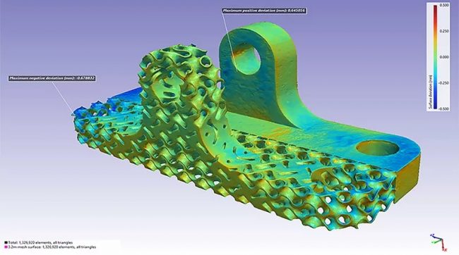
The accuracy of the image-based model was used to carry out a deviation analysis with the original CAD design. Simpleware software’s landmarking and automatic registration tools were employed to align the two parts, before using the software’s deviation analysis tool to identify key differences between them. This method resulted in previously undetected problems in the manufacturing process being picked up on, allowing researchers to factor them in to future design iterations of the component.
Finally, the FE volume mesh was imported to ANSYS Mechanical software in order to run a structural simulation on the performance of the original CAD design and the CT-scanned part. The simulation solved mechanical loading problems and verified that the deviations between the original and as-manufactured design did not affect the performance of the component to specifications.
![]() Re-Testing the Workflow with Moog, Inc.
Re-Testing the Workflow with Moog, Inc.
The same workflow was developed for Moog, Inc, for their research into designing, manufacturing, and integrating precision motion control; products and systems for industries such as automotive and aerospace. Moog use a CAD workflow to design and test potential parts using ANSYS Mechanical before printing on a Renishaw AM250 laser-powder-bed-fusion (LPBF) machine. For this project, which involved designing an impulse pressure manifold with a specific material and hydraulic fluid configuration, the Synopsys-NSI-ANSYS workflow was used to inspect and simulate performance.
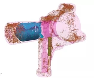 Impulse pressure model showing interior detail
The AM manifold was CT-scanned by North Star Imaging prior to segmentation in Simpleware software. Visualization of the internal features of the scanned part revealed pores, cracks, and residual powder from the manufacturing process. When compared with the original CAD design, geometric deviations such as part porosity could also be revealed. FE meshes were generated from the CAD and segmented CT data to simulate maximum principal stress in ANSYS Mechanical. An increase in maximum principal stress was identified between the CAD design and the AM part, with changes likely occurring due to the presence of cracks and pores. The results were used by Moog to inform their design iterations and the manufacturing quality of their AM parts, with the goal of reducing the risk of performance uncertainty.
![]() Taking the Method Further
Taking the Method Further
The two case studies from this workflow show the potential of linking CT-based inspection, simulation, and AM to improve design and manufacturing decision-making. One of the key benefits of the workflow was its speed and the ability to accurately compare CAD and image-based models through deviation analysis. Manufacturers can therefore benefit from increased knowledge of errors during part design, and how these can be mitigated or removed to make metal and other AM workflows more efficient in terms of work-time, material usage, measurement accuracy, and cost.
Source:metrology
Recent Comments